













Daftar Isi
Introduction
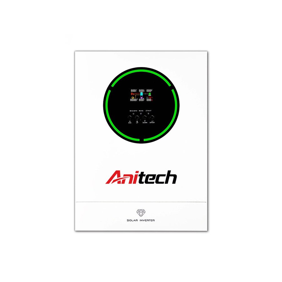
A photovoltaic inverter is one of the most influential components in a solar power system. Although photovoltaic modules determine how much DC electricity can potentially be generated, the inverter determines whether that energy can be converted, controlled, monitored, and delivered efficiently within the electrical limits of the complete system.
Many inverter-related problems do not begin with defective equipment. They begin during system design. An inverter may have an appropriate rated output but still be poorly matched to the PV string voltage, module current, MPPT configuration, phase structure, environmental conditions, or future energy-storage requirements. These mismatches can reduce usable generation, complicate commissioning, or limit future system expansion.
This article examines seven common photovoltaic inverter mistakes from a system-design perspective. Rather than focusing only on individual product specifications, it explains how PV modules, inverter inputs, AC loads, monitoring functions, installation conditions, and storage requirements should work together as one coordinated electrical system.
Why Photovoltaic Inverter Selection Has Become More Complex
Earlier photovoltaic systems were often designed around a relatively simple energy path. Solar modules generated DC electricity, the inverter converted it into AC electricity, and the resulting power was used by local loads or synchronized with the grid. In that architecture, inverter evaluation concentrated heavily on rated power, conversion efficiency, and basic input limits.
Modern systems often involve more variables. A photovoltaic inverter may need to work with several PV strings, multiple MPPT channels, changing module technologies, smart monitoring, battery storage, backup circuits, export management, or different operating schedules. Each additional function creates another compatibility relationship that needs to be checked during system planning.
This means the inverter should no longer be treated as an isolated box between the modules and the AC system. It acts as the electrical interface between generation and consumption. Understanding the broader role of a photovoltaic system helps explain why inverter compatibility has such a strong influence on overall system behavior.
The best photovoltaic inverter is therefore not automatically the model with the largest output or longest feature list. It is the inverter whose electrical limits and control functions match the intended PV array and operating environment.
Mistake 1: Choosing a Photovoltaic Inverter Only by Rated Power
Rated AC output is an important specification, but using it as the primary selection criterion can hide other limitations. Two photovoltaic inverter models with the same nominal power may support very different PV voltages, input currents, MPPT configurations, phase arrangements, and operating environments.
For example, an inverter may have enough AC output for the expected electrical demand while its PV input current is too low for the selected modules. Another unit may support the required PV capacity but have an MPPT range that does not match the intended string configuration. In both cases, rated kilowatts alone would suggest compatibility even though the electrical design tells a different story.
A more reliable approach begins by treating rated power as one parameter within a larger compatibility framework. PV string voltage, module current, expected load demand, phase configuration, battery requirements, environmental conditions, and future expansion should all be evaluated before the final inverter capacity is chosen.
This system-level approach is especially important when comparing a broad solar inverter product range, because models with similar output ratings may be intended for different PV architectures and applications.
Mistake 2: Ignoring the MPPT Operating Range
Maximum Power Point Tracking allows the photovoltaic inverter to adjust its electrical operating point as solar conditions change. Since module voltage varies with temperature, irradiance, shading, and other environmental factors, the inverter needs an appropriate voltage window in which it can effectively track the connected PV array.
One common mistake is checking only the inverter’s maximum DC input voltage. Remaining below that maximum does not necessarily mean the PV string has been designed correctly. The normal operating voltage should also remain within the specified MPPT range under realistic operating conditions.
Suppose a PV string has a voltage that is technically safe but regularly falls near or below the lower MPPT boundary. The system may not operate as effectively as a string designed to remain comfortably within the tracking range. Conversely, adding too many modules in series can push open-circuit voltage too close to the inverter’s upper input limit under certain environmental conditions.
A well-designed photovoltaic inverter system therefore considers both safety limits and normal operating limits. Module open-circuit voltage, operating voltage, temperature effects, string length, and MPPT range should be assessed together rather than as separate specifications.
Mistake 3: Overlooking PV Input Current
As photovoltaic module technology develops, module current has become an increasingly important part of inverter compatibility. A system may appear correctly sized in terms of total wattage while still exceeding the allowable current of an inverter input or MPPT channel.
This issue becomes particularly important when PV strings are connected in parallel. Series connection increases voltage, while parallel connection increases current. Adding another parallel string can therefore alter inverter compatibility even when individual string voltage remains unchanged.
The module’s operating current and short-circuit current should be compared with the inverter’s maximum allowable input current and MPPT current limits. Appropriate design margins should also be considered according to the complete electrical architecture and applicable installation requirements.
This is one reason total PV wattage should never be used as a substitute for electrical design. A photovoltaic inverter does not receive “watts” in isolation; it receives voltage and current from a specific string configuration. Those electrical characteristics must remain inside the inverter’s supported operating limits.
Mistake 4: Treating All MPPT Channels as Interchangeable
Multiple MPPT channels can provide useful design flexibility, particularly when different sections of the photovoltaic array operate under different conditions. However, simply having several trackers does not automatically mean any combination of strings can be connected without additional planning.
PV groups installed at different orientations, exposed to different shading patterns, or built with different string lengths may have different optimum operating points. Independent MPPT channels can allow these groups to be controlled separately, reducing the extent to which one array condition influences another.
The mistake occurs when significantly different strings are placed on the same tracker without considering their electrical behavior. Although the exact acceptable configuration depends on the inverter design, grouping electrically similar strings generally creates a more predictable operating environment.
For this reason, MPPT planning should follow the physical layout of the PV array. Roof orientation, module count, shading exposure, string voltage, and current should be mapped before strings are assigned to the inverter. The result is a clearer relationship between the physical solar array and the inverter’s internal tracking architecture.
Key Photovoltaic Inverter Parameters to Check Together
Photovoltaic inverter specifications are most useful when they are interpreted as connected limits. Looking at one parameter without considering the others can create a design that appears correct on paper but performs differently in real operation.
| Parameter | What It Affects | Main Design Question |
|---|---|---|
| Rated AC output | Usable AC power | Does it match realistic electrical demand? |
| Maximum DC voltage | PV-side safety limit | Will string voltage remain below the limit? |
| Rentang tegangan MPPT | Normal PV operation | Will strings remain within the tracking window? |
| Maximum input current | Module compatibility | Can the inverter accept the selected PV current? |
| Number of MPPTs | Array flexibility | Do different PV groups need independent tracking? |
| AC phase configuration | Power distribution | Does output match the electrical system? |
| Conversion efficiency | Energy conversion | How does performance vary across operating conditions? |
| Monitoring capability | Diagnostics | Can system behavior be understood clearly? |
| Battery interface | Storage integration | Is future or current storage supported? |
| Environmental rating | Installation suitability | Can the inverter operate reliably at the installation site? |
The important point is not to identify the “best” number in every row. The objective is to find a photovoltaic inverter whose specifications form a compatible group for the intended system.
Mistake 5: Assuming Peak Efficiency Represents Real System Performance

Maximum efficiency is often highlighted prominently in inverter specifications, which can make it appear to be the most important indicator of performance. Efficiency certainly matters, because every conversion stage introduces some energy loss, but a single peak value does not describe how an inverter behaves throughout an entire operating day.
A photovoltaic inverter operates across different input voltages, power levels, temperatures, and solar conditions. Morning operation may occur at relatively low power, midday operation may approach higher output, and changing cloud cover can cause repeated shifts in operating conditions. The inverter’s actual performance is therefore influenced by much more than its maximum published efficiency.
MPPT effectiveness, standby consumption, thermal behavior, PV string design, input voltage, and operating power all contribute to real system results. An inverter with excellent peak efficiency cannot compensate for a poorly configured PV array that regularly operates outside the most suitable tracking range.
Efficiency should therefore be interpreted within the wider electrical design. A balanced photovoltaic inverter configuration usually delivers more practical value than selecting equipment around one headline percentage while overlooking voltage, current, MPPT, or installation compatibility.
Mistake 6: Ignoring the Installation Environment
A photovoltaic inverter is an electronic power-conversion device that generates heat during normal operation. Its installation environment can therefore influence operating temperature, cooling performance, reliability, and available output.
Ventilation is particularly important. If airflow around the inverter is restricted, internal temperature may rise and thermal management systems may need to reduce output to protect internal components. Installation clearances and ventilation requirements should therefore be treated as part of the system design rather than simply as mounting instructions.
Dust, moisture, ambient temperature, direct environmental exposure, and installation position also deserve attention. An enclosure protection rating can indicate resistance to certain environmental conditions, but it should not be interpreted as permission to ignore ventilation, drainage, thermal stress, or the manufacturer’s specified installation limits.
Cable routing and electrical protection are also closely connected to the physical installation. Long cable runs, undersized conductors, poor connections, or unsuitable protective devices can introduce voltage drop, heating, and operating problems even when the photovoltaic inverter itself is correctly selected.
Reliable operation therefore depends on both equipment design and installation quality.
Mistake 7: Forgetting About Future Battery Storage and System Expansion
A photovoltaic system may initially be designed without battery storage, but future requirements can change. Additional PV modules, energy storage, backup loads, or expanded electrical demand may eventually become part of the same system.
The mistake is not failing to predict every possible future change. The mistake is ignoring realistic expansion plans that are already known during the original design stage.
If battery storage is likely to be introduced, inverter architecture becomes particularly important. Storage integration may require compatible voltage ranges, charging and discharging capability, communication with a Battery Management System, and suitable energy-management modes. An inverter designed only for straightforward grid-connected PV operation may require a different system architecture if storage is added later.
Future PV expansion should also be considered. Available MPPT channels, PV input current, maximum DC capacity, and string configuration can determine whether additional modules can be integrated efficiently.
The objective is not unlimited oversizing. It is sensible flexibility. A photovoltaic inverter should match current requirements while leaving room for realistic development where future expansion is part of the intended system plan.
How Battery Storage Changes Photovoltaic Inverter Design
Battery storage introduces a second DC energy source into the system and changes the inverter’s responsibilities significantly. Instead of only receiving electricity from photovoltaic modules and converting it to AC power, a storage-capable system may need to coordinate solar generation, battery charging, battery discharge, electrical loads, and grid interaction.
Battery compatibility begins with voltage but extends much further. Maximum charging current, discharge current, battery chemistry, BMS communication, state-of-charge limits, and operating strategy can all affect how the storage system behaves.
Power and energy should also be distinguished. Battery energy capacity indicates how much stored electricity is available, while battery power capability determines how quickly that electricity can be delivered. A battery may contain substantial energy but still be unable to supply the instantaneous current expected by the inverter during high-demand operation.
This is why future storage plans should influence photovoltaic inverter selection. The inverter and battery should ultimately function as one coordinated electrical system rather than two independent devices connected after separate selection processes.
Single-Phase vs Three-Phase Photovoltaic Inverter Selection
Phase configuration should match the electrical distribution system and actual load requirements. A single-phase photovoltaic inverter is appropriate for many single-phase electrical architectures, while three-phase inverters are designed to distribute output across three phases.
Three-phase systems require additional consideration because total inverter capacity does not always describe what can occur on each individual phase. Electrical loads may be unevenly distributed, and some inverters permit more imbalance than others.
This becomes particularly important when backup operation or large electrical equipment is involved. An installation may remain within total inverter output while one phase experiences significantly greater demand. If phase-level limits are not considered during design, available system capacity may not be used effectively.
A reliable selection process therefore considers total AC demand and phase distribution together. The phase configuration is not simply a product feature; it is part of the overall electrical architecture.
A Better Four-Zone Method for Evaluating a Photovoltaic Inverter
A practical way to evaluate inverter compatibility is to divide the system into four zones. This framework helps prevent one attractive specification from dominating the selection decision.
The first zone is PV input compatibility. This includes string voltage, operating current, maximum DC input, MPPT range, and tracker configuration. The objective is to make sure the photovoltaic array can operate safely and effectively within the inverter’s electrical limits.
The second zone is conversion and AC output. Here, rated output, phase type, operating efficiency, startup behavior, and connection requirements should be compared with the intended electrical system.
The third zone is control and monitoring. A photovoltaic inverter should provide enough operational visibility to support commissioning, performance review, and fault diagnosis. Monitoring becomes increasingly important as system architecture becomes more complex.
The fourth zone is future integration. Battery storage, backup requirements, PV expansion, and load growth should be considered if they form part of a realistic future plan.
An inverter that performs well across all four zones is generally a stronger match than one chosen because it leads in only one specification.
Why Monitoring Matters More Than Many Users Expect
Monitoring should not be treated as a decorative feature. In a modern PV system, operational data can help explain why actual behavior differs from expectations.
If generation appears lower than anticipated, useful inverter data may reveal differences between PV inputs, operating voltage, MPPT performance, temperature conditions, or active system alarms. When several PV strings are involved, input-level data can make it easier to identify whether a performance issue affects the entire system or only one section of the array.
Storage-capable installations add another layer of complexity because electricity can move between PV generation, batteries, loads, and the grid. Monitoring helps make these energy flows visible, which can improve commissioning and ongoing system management.
The quality of monitoring should therefore be judged by whether the information helps users understand and diagnose the photovoltaic system, rather than simply by whether remote access is available.
How to Match a Photovoltaic Inverter to the PV Array
A reliable matching process starts with the module datasheet and intended string layout. The number of modules connected in series determines string voltage, while parallel strings influence current. These values should then be checked against the inverter’s maximum DC voltage, MPPT range, and input-current limits.
Environmental variation should be included in this assessment. Module voltage changes with temperature, so a string that appears suitable under nominal test conditions may operate differently in real environments. System design should therefore include appropriate electrical margins rather than relying on one fixed operating value.
The physical layout should then be compared with the MPPT architecture. Arrays with different orientations or electrical conditions may benefit from separate trackers, while electrically similar strings can often be grouped more naturally.
Finally, the AC side should be checked against actual system demand. This creates a complete design path from the PV modules through the photovoltaic inverter to the electrical loads.
Common Signs of a Poorly Matched Photovoltaic Inverter System
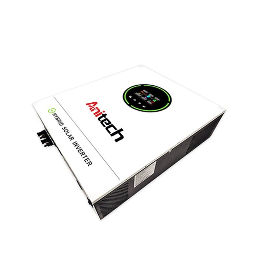
A poorly matched system does not always fail completely. In many cases, it simply performs less effectively than expected.
One possible sign is that PV strings frequently operate near the limits of the inverter’s MPPT range. Another is repeated input-current limitation when high-current modules are used. Unexplained differences between PV inputs can also indicate string or MPPT configuration issues.
Thermal output reduction may point toward installation-environment problems, while repeated communication problems in storage systems can indicate inverter and battery incompatibility. Phase-related limitations may appear when loads are unevenly distributed in a three-phase architecture.
These symptoms should not automatically be blamed on the inverter itself. In many cases, they are signs that individual components have not been matched correctly as a complete system.
This distinction is important because replacing one component without identifying the underlying compatibility problem may simply move the issue rather than solve it.
Kesimpulan
A photovoltaic inverter should never be selected on rated power alone. PV string voltage, module current, MPPT configuration, phase structure, real operating efficiency, installation environment, monitoring capability, battery compatibility, and future expansion all influence how effectively the inverter performs within the complete photovoltaic system.
The seven mistakes discussed in this article share one common cause: treating specifications independently instead of evaluating how they interact. An inverter may look technically impressive in isolation but still become a limiting point when connected to an incompatible array or electrical architecture.
The stronger approach is to design from the system outward. Define the PV strings, understand the load profile, establish phase requirements, consider realistic future storage, and then choose a photovoltaic inverter whose electrical limits and control functions support those requirements together.
When the inverter, PV array, loads, and supporting components are correctly matched, the system has a much stronger foundation for stable operation, effective energy conversion, and future development.
FAQ
What is a photovoltaic inverter?
A photovoltaic inverter converts DC electricity generated by PV modules into AC electricity suitable for compatible electrical loads and system operation. It can also manage MPPT, monitoring, protection, grid synchronization, and, in suitable designs, battery and backup functions.
How do I choose the right photovoltaic inverter?
Start with PV string voltage, current, MPPT requirements, and actual AC load demand. Then evaluate phase configuration, efficiency, environmental conditions, monitoring, storage requirements, and future expansion. The best inverter is the one that matches the complete system.
Why is MPPT important in a photovoltaic inverter?
MPPT adjusts the PV array’s electrical operating point as sunlight, temperature, and other conditions change. A suitable MPPT voltage range and tracker configuration help the inverter operate effectively with the connected strings under changing real-world conditions.
Can a photovoltaic inverter work with battery storage?
Some photovoltaic inverter architectures are designed for battery integration, while others focus primarily on direct PV-to-AC conversion. Storage compatibility depends on inverter design, battery voltage, charge and discharge limits, BMS communication, and supported operating modes.
Does a larger photovoltaic inverter always improve performance?
No. A larger rated output does not solve mismatched PV voltage, excessive input current, unsuitable MPPT configuration, battery limitations, or phase imbalance. Inverter size should be selected according to the complete electrical design rather than maximum capacity alone.
Need Help Choosing the Right Photovoltaic Inverter?
If you’re unsure which photovoltaic inverter best matches your PV array, MPPT configuration, electrical loads, phase requirements, storage plans, or future system expansion, our technical team can help evaluate the key compatibility factors. Build your photovoltaic system around components that are designed to operate together reliably and support the intended application over the long term.